Free Preparation Discussions
Dell EMC D-PSC-MN-01 Exam Questions
- Topic 1: PowerScale Hardware Concepts: This part of the exam assesses the expertise of IT infrastructure architects, and emphasizes the ability to differentiate between the architectural elements of PowerScale platforms, understand their specific use cases, and compare design specifications across PowerScale hardware models.
- Topic 2: PowerScale Hardware Maintenance: Targeted at system administrators, this section focuses on key tasks involved in maintaining PowerScale hardware. It examines candidates' proficiency in completing initial maintenance steps, preparing nodes for operation, and processing Field Replaceable Unit (FRU) and Customer Replaceable Unit (CRU) requests.
- Topic 3: PowerScale Hardware Installation: This section evaluates the installation capabilities of hardware engineers to test candidates on their ability to plan and execute the installation of PowerScale hardware, prepare the maintenance site, and adhere to best practices when installing racks, nodes, and related components.
- Topic 4: PowerScale Implementation: Geared towards cluster administrators, this section covers the practical aspects of implementing PowerScale systems. It focuses on creating new clusters, integrating nodes into existing clusters, and applying alternative configurations or accessories to improve performance.
Free Dell EMC D-PSC-MN-01 Exam Actual Questions
Note: Premium Questions for D-PSC-MN-01 were last updated On Jul. 06, 2026 (see below)
Refer to the exhibit.
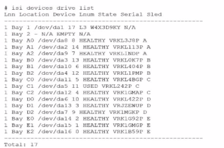
An engineer replaced the drive in C1. They run the isi devices drive list command and obtain the output that is shown.
What action must the engineer take?
In the output of the isi devices drive list command shown in the exhibit, the drive in location C1 is marked as 'USED,' with the serial number VRKL242P. This indicates that the drive has been replaced but has not yet been initialized or formatted for use within the PowerScale cluster.
To make the drive usable, it must be formatted. The correct procedure to follow is to use the isi devices drive format command, specifying the drive location (C1 in this case). This will prepare the drive for use in the cluster, ensuring that it is recognized and available for OneFS to start writing data to it.
Steps to format the drive:
Log in to the OneFS cluster using an SSH session with an account that has the necessary privileges.
Run the following command to format the new drive:
bash
Copy code
isi devices drive format C1
This command will format the drive located at C1, making it available for use in the cluster.
After the format is complete, verify that the drive is now in a HEALTHY state by running:
isi devices drive list
This should display the new status of the drive as HEALTHY, indicating that it has been successfully formatted and is ready for data operations.
This process is outlined in Dell's PowerScale Administration Guide and ensures the correct initialization of new or replaced drives.
Which statement is accurate regarding Dell EMC PowerScale hardware platforms?
Dell EMC PowerScale Gen 6 nodes are available in different form factors to meet various storage and performance needs.
Gen 6 Node Form Factors:
2U Chassis:
Models like the F800 and H500.
Designed for high performance with moderate capacity.
4U Chassis:
Models like the A2000.
Offer high-density storage options.
Clarifications:
Option A: Incorrect, as Gen 6 nodes come in both 2U and 4U chassis.
Option B: Incorrect, Gen 6.5 F200 nodes come in a 1U chassis.
Option D: Incorrect, F600 nodes can be added individually, not only as pairs.
Dell PowerScale Reference:
Dell EMC PowerScale Technical Specifications:
Lists models with their corresponding chassis sizes.
Provides detailed hardware descriptions.
Best Practices:
Plan rack space according to the chassis size of the nodes being deployed.
Consider power and cooling requirements based on node specifications.
What type of privileges are required to perform tenant-specific administration?
Tenant-specific administration involves managing specific zones or tenants within a Dell EMC PowerScale environment. This requires a certain level of privileges that allows administrators to control resources without having full system-wide access.
Zone Role-Based Access Control:
Definition:
Zone role-based access control allows administrators to assign permissions to users or groups for specific zones or tenants.
Functionality:
Enables delegation of administrative tasks within a particular zone without granting system-wide privileges.
Benefits:
Enhances security by limiting access.
Simplifies management in multi-tenant environments.
Why Other Options Are Incorrect:
System Root Privileges (Option B):
Root privileges grant full access to the entire system, which is not necessary for tenant-specific tasks.
System Admin Privileges (Option C):
Similar to root, system admin privileges are broader than needed.
Role-Based Access Control (Option D):
While general role-based access control is related, zone role-based access control is specifically designed for tenant administration.
Dell PowerScale Reference:
Dell EMC PowerScale OneFS Administration Guide:
Chapter on Access Control and Authentication:
Details how to implement zone role-based access control.
Provides instructions on assigning roles to users within specific zones.
Best Practices:
Regularly review and update access permissions.
Use the principle of least privilege to enhance security.
An engineer runs ini_reformat_node command.
What are they attempting to do?
The isi_reformat_node command is a utility used on Dell PowerScale (Isilon) clusters to reformat a node and securely erase all data on it. This command initializes the node's storage media, effectively wiping all user data, metadata, and system configurations from the node's drives.
Purpose of isi_reformat_node:
Secure Data Erasure: It ensures that all data is securely erased, which is essential when decommissioning a node or repurposing it for a different use.
Node Recovery or Repurposing: It prepares the node for re-integration into the cluster or for use in a different cluster by resetting it to a factory-like state.
Usage Scenarios:
Decommissioning a Node: When permanently removing a node from a cluster and ensuring no residual data remains.
Repurposing Hardware: When reassigning the node to a different cluster or role and needing to eliminate all previous configurations and data.
Recovering from Corruption: In cases where the node's data is irreparably corrupted, reformatting allows for a clean start.
Key Points:
Data Loss Warning: Running isi_reformat_node will result in complete data loss on that node. It's crucial to ensure that the data is backed up or that the node's data is no longer needed.
Cluster Impact: Before reformatting, the node should be appropriately prepared, and the cluster should be informed to avoid any data protection issues.
Secure Erasure Standards: The command follows secure erasure standards to prevent data recovery through forensic methods.
Dell PowerScale OneFS CLI Administration Guide -- Details on using isi_reformat_node and its implications.
Dell PowerScale OneFS Administration Guide -- Procedures for safely removing and reformatting nodes.
Dell Knowledge Base Article -- Best practices for decommissioning and reformatting nodes in a PowerScale cluster.
What is a consideration when reimaging a Dell PowerScale node?
When reimaging a Dell PowerScale node, an important consideration is to perform the reimage on a node that is not a member of a cluster. Reimaging a node that is part of a cluster can lead to data loss and cluster instability. Therefore, the recommended practice is to remove the node from the cluster before initiating the reimage process.
1. Understanding Reimaging:
Reimaging Process:
Reimaging involves reinstalling the OneFS operating system on a node.
It effectively returns the node to a factory-default state.
All data and configurations on the node are erased during the process.
Purpose of Reimaging:
Used to address software corruption, persistent errors, or to prepare a node for redeployment.
2. Importance of Performing Reimage on a Non-Clustered Node:
Data Protection:
Reimaging a node within a cluster can disrupt data protection schemes.
The node's data may not be fully replicated elsewhere, risking data loss.
Cluster Integrity:
Removing the node ensures that the cluster remains stable and avoids potential conflicts.
The cluster's metadata and configuration remain consistent.
Recommended Procedure:
Step 1: Remove the node from the cluster using the appropriate OneFS commands or the WebUI.
Step 2: Confirm that the cluster recognizes the node removal and data has been reprotected.
Step 3: Proceed with reimaging the node.
3. Why Other Options Are Less Suitable:
Option B: Reimaging does not erase the data and is faster.
Incorrect; reimaging erases all data and configurations on the node.
It is not necessarily faster and involves careful steps to ensure data integrity.
Option C: Perform on a node that is a member of a cluster.
Not recommended due to risks of data loss and cluster instability.
Best practices dictate removing the node first.
Option D: Use the rolling reimage update to retain the current OneFS version.
There is no 'rolling reimage update' process.
Rolling upgrades are for updating OneFS versions, not reimaging nodes.
4. Dell PowerScale Best Practices:
Node Removal Before Reimaging:
Always remove the node from the cluster before reimaging.
Ensure the cluster is healthy and data is fully protected.
Backup Critical Data:
Verify that critical data is backed up or replicated.
5. Dell PowerScale Reference:
Dell EMC PowerScale OneFS Administration Guide:
Provides instructions on managing nodes and reimaging procedures.
Dell EMC PowerScale OneFS Administration Guide
Dell EMC PowerScale OneFS CLI Administration Guide:
Details commands for removing nodes and reimaging.
Dell EMC PowerScale OneFS CLI Guide
Knowledge Base Articles:
Article ID 000180125: 'Best Practices for Reimaging PowerScale Nodes'
Article ID 000180126: 'Procedures for Safely Reimaging a Node'
- Select Question Types you want
- Set your Desired Pass Percentage
- Allocate Time (Hours : Minutes)
- Create Multiple Practice tests with Limited Questions
- Customer Support
David Cooper
5 days agoMonica Roberts
23 days agoAdam Williams
1 month agoAdam Ramirez
2 months agoBrian Walker
2 months agoHeather Jackson
3 months agoTiffany Mitchell
2 months agoMelissa Garcia
2 months agoJoseph Clark
2 months agoBrian Brown
3 months agoJennifer Collins
2 months agoSalley
3 months agoWilford
4 months agoDylan
4 months agoBenton
4 months agoThaddeus
4 months agoOctavio
5 months agoMarg
5 months agoJoye
5 months agoChantay
5 months agoRebbecca
6 months agoRebbecca
6 months agoNadine
6 months agoShizue
6 months agoGlendora
7 months agoAltha
7 months agoLenna
7 months agoBrynn
7 months agoAleta
8 months agoMarguerita
8 months agoEura
8 months agoArdella
8 months agoLang
9 months agoLore
9 months agoChau
9 months agoDerick
9 months agoTwana
10 months agoIola
10 months agoMalcolm
10 months agoTijuana
10 months agoStephaine
10 months agoRaul
10 months agoLeontine
10 months agoJaime
1 year agoDalene
1 year agoLourdes
1 year agoAlecia
1 year agoAlyce
1 year agoRicarda
1 year agoLeonor
1 year agoGlory
1 year agoLizbeth
1 year agoClare
1 year agoNoe
1 year agoTequila
1 year agoLashawnda
1 year agoJose
1 year agoHildegarde
1 year agoWilbert
1 year agoJerrod
1 year agoVal
2 years agoHoney
2 years agoCherry
2 years agoSkye
2 years agoBenton
2 years agoOna
2 years agoWillard
2 years agoHester
2 years agoFranchesca
2 years agoBelen
2 years agoMalinda
2 years agoVincent
2 years agoMozell
2 years agoAbraham
2 years agoZita
2 years agoHollis
2 years ago