Deal of The Day! Hurry Up, Grab the Special Discount - Save 25% - Ends In 00:00:00 Coupon code: SAVE25

Free Preparation Discussions
 MENU
MENU
Cisco 200-301 Exam - Topic 10 Question 54 Discussion
Actual exam question for
Cisco's
200-301 exam
Question #: 54
Topic #: 10
[All 200-301 Questions]
Topic #: 10
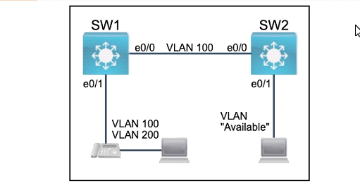
Refer to the exhibit.
All physical cabling between the two switches is installed. Configure the network connectivity between the switches using the designated VLANs and interfaces.
1. Configure VLAN 100 named Compute and VLAN 200 named Telephony where required for each task.
2. Configure Ethernet0/1 on SW2 to use the existing VLAN named Available.
3. Configure the connection between the switches using access ports.
4. Configure Ethernet0/1 on SW1 using data and voice VLANs.
5. Configure Ethemet0/1 on SW2 so that the Cisco proprietary neighbor discovery protocol is turned off for the designated interface only.
Suggested Answer:
A
Esteban
10 months agoKathrine
10 months agoGary
10 months agoShad
11 months agoNadine
11 months agoLouvenia
11 months agoJody
11 months agoDeeann
11 months agoAmber
11 months agoWade
11 months agoJodi
11 months agoDerrick
11 months agoLonny
11 months ago