Free Preparation Discussions
AutoDesk RVT_ELEC_01101 Exam - Topic 1 Question 10 Discussion
Topic #: 1
Refer to exhibit.
(The image is presented in Imperial units: 1 In = 25 mm [Metric units rounded].)
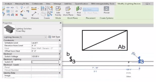
An electrical designer is trying to add the selected three-way switch to the existing switch system "b". The designer is unable to add the switch to the switch system.
Why is this problem occurring?
In Autodesk Revit Electrical Design, lighting control systems such as single-pole, three-way, and four-way switches are managed using Switch Systems. These systems logically connect lighting devices (switches) to the lighting fixtures they control. For multiple switches (like three-way configurations) to be part of the same control circuit, they must share the same Switch ID value.
In the exhibit, the electrical designer is attempting to add a three-way switch to the existing switch system labeled ''b'', but Revit does not allow it. The reason is that the Switch ID parameter of the new switch does not match the Switch ID of the system it is intended to join.
The Switch ID acts as the unique identifier that links all switches controlling the same group of fixtures. If the IDs differ (for example, ''b3'' versus ''b''), Revit interprets them as belonging to separate systems and prevents them from being grouped together.
The Autodesk Revit MEP User's Guide -- Electrical Systems: Lighting and Switch Systems explains this clearly:
''Switch systems are organized by Switch ID. All switches controlling the same lighting circuit must have identical Switch ID values. Revit will not allow a switch to be added to an existing system if its Switch ID does not match that system's identifier.''
To fix this, the designer must: 1 Select the three-way switch. 2 In the Properties palette, locate the Switch ID parameter. 3 Change its value to match the target switch system's ID (in this case, ''b'').
Once both switches share the same Switch ID, Revit will successfully include them in the same Switch System.
Toi
5 hours agoJamika
5 days agoTori
11 days agoNoemi
16 days agoShenika
2 months agoMarilynn
2 months agoTimmy
3 months agoMaybelle
3 months agoErnest
3 months agoOmer
4 months ago