Free Preparation Discussions
AutoDesk RVT_ELEC_01101 Exam Questions
- Topic 1: Modeling: This section of the exam measures the skills of Electrical Designers and covers creating and managing electrical elements within Revit. It includes adding electrical equipment such as panelboards and transformers, configuring circuits and low-voltage systems, and using the System Browser for navigation. Candidates must also demonstrate the ability to model connecting geometry, including conduits, cable trays, and wiring, with appropriate settings and fittings.
- Topic 2: Documentation: This section of the exam measures the skills of Revit Technicians and covers manipulating views, templates, and schedules to produce accurate documentation. It includes managing panel schedules, creating various view types such as legends, callouts, and 3D views, and applying phasing and revision management. Candidates are also tested on annotation tools, including tags, keynotes, and note blocks, to ensure clarity and consistency in project documentation.
- Topic 3: Families: This section of the exam measures the skills of BIM Modelers and focuses on creating and editing Revit families. It includes defining MEP connectors, understanding system and component family types, configuring family categories, and setting up light sources. The section also assesses parameter creation, annotation family setup, and controlling element visibility to ensure effective customization and reuse across electrical projects.
- Topic 4: Analysis: This section of the exam measures the skills of Electrical Engineers and focuses on performing analytical tasks in Revit. It includes conducting load calculations, conceptual lighting analysis, and configuring electrical settings for load classifications and demand factors. Candidates must show the ability to use Revit’s analysis tools to ensure proper electrical design performance and energy efficiency.
- Topic 5: Collaboration: This section of the exam measures the skills of Project Coordinators and covers collaboration workflows in Revit. It includes working with imported and linked files, managing worksharing concepts, and using interference checks. Candidates are also evaluated on data coordination through copy/monitor tools, exporting to different formats, managing design options, and transferring project standards to ensure effective teamwork in shared environments.
Free AutoDesk RVT_ELEC_01101 Exam Actual Questions
Note: Premium Questions for RVT_ELEC_01101 were last updated On Jun. 09, 2026 (see below)
Refer to exhibits.
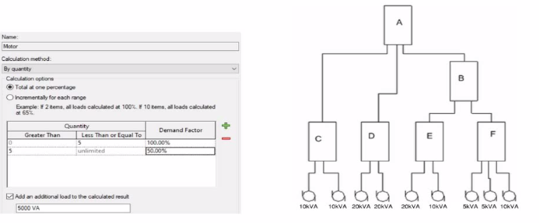
What is the demand load on Panel B?
In Revit Electrical, Demand Factors are applied through Load Classifications to compute an Estimated Demand Load rather than simply summing connected loads. The documentation states: ''You use demand factors to adjust the rating of the main service... Demand factors are assigned to load classifications, and load classifications are assigned to device connectors. The estimated load for a device is calculated by multiplying the load by the demand factor. ... The panel schedule can also display the load for each load classification.''
In the exhibit's Demand Factor definition (for the Motor classification), the Calculation method is By quantity with Total at one percentage selected. Two quantity ranges are defined: 0--5 items at 100% and 5--unlimited at 50%. An additional checkbox adds an extra fixed load of 5000 VA to the calculated result. (This follows Revit's behavior of applying the selected demand factor to the connected load and then adding any specified additional load to the result for that classification.)
Panel B feeds only panels E and F. The connected motor loads downstream are:
Panel E: 20 kVA + 10 kVA = 30 kVA
Panel F: 5 kVA + 5 kVA + 10 kVA = 20 kVA
Total connected motor load on B = 30 + 20 = 50 kVA (five items).
Because five items fall in the 0--5 range at 100%, the demand factor is 100% 50 kVA. Per the definition, add an additional load of 5000 VA (5 kVA) to the calculated result:
Demand Load on Panel B = 50 kVA 100% + 5 kVA = 55 kVA.
Therefore, the correct choice is 55 kVA.
References: Revit MEP Electrical documentation -- Demand Factors (assignment to load classifications, multiplication to compute estimated load, and display in panel schedules).
An electrical designer wants to schedule parameters from generic annotations Which type of schedule must be created?
When an electrical designer wants to schedule parameters from Generic Annotations, the correct method is to use a Note Block, not a generic schedule. Revit documentation defines this process clearly under Annotation Schedules (Note Blocks):
''Annotation schedules, or note blocks, list all instances of annotations that you can add using the Symbol tool.'' ''Creating an Annotation Schedule (Note Block):
Load the generic annotation family or families into your project and place them where desired.
Click View tab Create panel Schedules drop-down Note Block.
In the New Note Block dialog, for Family, select a generic annotation.''
This extract confirms that when working with generic annotation families, Revit requires the use of a Note Block to extract and list their parameters in a schedule. Standard schedules such as Generic Model or Family schedules cannot access data from Generic Annotations since they are annotation-based, not model-based.
An electrical designer is trying to adjust the scale of a view. All icons on the View Control Bar are dimmed (not enabled). How should the designer make the view scale editable only for this view?
When all icons on the View Control Bar are dimmed (disabled), including the View Scale, it typically means the view is being controlled by a View Template. View templates apply standardized settings---such as scale, discipline, detail level, and more---across multiple views to ensure consistency. However, these templates can lock certain parameters, including the view scale, preventing manual changes.
According to Revit Electrical Design standards:
'If a view is governed by a View Template, properties such as view scale may be locked and appear dimmed in the View Control Bar. To regain control and allow changes like adjusting the view scale, the view template must be removed. This is done by setting the View Template to <None> in the Properties Palette.'
Steps:
Select the view in question.
Open the Properties Palette.
Locate the View Template parameter.
Set it to <None>.
Now the View Control Bar becomes active and the scale can be changed freely.
Clarification of Other Options:
B (Edit the assigned view template): Changes apply to all views using that template, not just the one.
C (Duplicate the view with Detailing): Creates a copy but doesn't resolve template restrictions.
D (Right-click on the scale and select <Activate>): This is not a valid method in Revit.
Reference: This explanation aligns with the View Template behavior documented in Revit MEP and Electrical modeling workflows.
An electrical designer Is working on a workshared model.
Which two worksharing display settings can the designer use to visualize model elements that have no ownership? (Select two.)
When working in a workshared Revit model, elements without ownership can be visually identified using Worksharing Display Settings.
As per Revit MEP Worksharing Guide -- Worksharing Display Modes section:
''Worksharing display modes include options such as Checkout Status, Owners, and Worksets. The Checkout Status mode shows elements that are not owned or are available for editing. The Owners mode highlights elements based on who owns them, allowing unowned elements to appear as 'none.'''
Therefore:
B. Checkout Status --- shows elements that are editable or not owned.
E. Owners --- displays which elements are owned and highlights those without ownership.
Incorrect options:
A . Worksets: Shows which workset an element belongs to, not ownership.
C . Gray Inactive Worksets: Only grays out inactive worksets.
D . Model Updates: Not a valid worksharing display setting.
Refer to exhibit.
(The Image is presented in Imperial units: 1 In = 25 mm [Metric units rounded).)

What is the electrical designer trying to do as shown in the exhibit?
The exhibit shown in the image is taken directly from the Revit MEP Electrical Systems workspace, specifically from the Parallel Conduits command interface. This dialog box appears when the designer activates the Place Parallel Conduits tool in the Systems tab Electrical panel Conduit dropdown Parallel Conduits.
In this interface, the designer can specify:
Horizontal Number / Offset -- defines how many conduits will be created horizontally and their spacing.
Vertical Number / Offset -- defines how many conduits will be created vertically and their spacing.
Bend Radius Options:
Same Bend Radius -- all conduits use identical bend radii.
Concentric Bend Radius -- conduits bend concentrically around a common center point.
According to Autodesk's Revit MEP 2011 User's Guide (Chapter 18, Electrical Systems -- Conduit Layout):
''The Parallel Conduits tool allows you to create multiple conduits side-by-side at the same time. You can specify the number of conduits horizontally and vertically, as well as the offset between them. You can also define whether bends have the same bend radius or concentric bend radii.'' --- Revit MEP User's Guide, Electrical Systems, Section: Conduit Layout
This tool is used when electrical designers need to route groups of conduits that run in parallel---such as power and data conduits running between panels or equipment racks. The Concentric Bend Radius option (as shown in the exhibit) ensures all conduit bends share a common center, which is critical for maintaining uniformity in conduit sweeps and avoiding clashes during coordination.
Therefore:
A . Add Cable Tray -- incorrect; the cable tray tool is separate and does not use bend radius options.
C . Array Conduit -- incorrect; arraying is a different geometric function not specific to conduit routing.
D . Place Multiple Pipe -- incorrect; applies to mechanical piping systems, not electrical conduits.
The display of Concentric Bend Radius, Horizontal Number, Vertical Number, and Offset confirms that the designer is using the Parallel Conduit placement tool.
Verified Reference Extracts from Revit Electrical Design Documentation:
Autodesk Revit MEP User's Guide (2011) -- Electrical Systems Conduit Layout ''Parallel Conduits Tool'' description.
Autodesk Revit MEP Training Curriculum -- Electrical Module, Exercise 6.3 ''Placing Parallel Conduits,'' which illustrates the same interface for bend radius configuration.
- Select Question Types you want
- Set your Desired Pass Percentage
- Allocate Time (Hours : Minutes)
- Create Multiple Practice tests with Limited Questions
- Customer Support
Nathan Gonzalez
14 days agoDaniel Nelson
27 days agoWilliam Phillips
1 month agoRebecca Roberts
2 months agoChristopher Johnson
1 month agoWilliam Evans
2 months agoGary Nguyen
1 month agoTimothy Garcia
1 month agoGerald Morgan
1 month agoCallie
2 months agoTeri
3 months agoDomingo
3 months agoNancey
3 months agoBernardo
3 months agoTaryn
4 months agoKing
4 months agoKyoko
4 months agoMagdalene
4 months agoDortha
5 months agoRonny
5 months agoMarsha
5 months agoGracia
5 months agoNieves
6 months agoDenise
6 months agoHoa
6 months agoBettina
6 months agoGenevive
7 months agoWillard
7 months agoOliva
7 months agoGracia
7 months agoAlishia
8 months agoElvera
8 months ago