
Free Preparation Discussions
 MENU
MENU
Nokia 4A0-265 Exam Questions
- Topic 1: Documentation and Support Information: Covers locating and using Nokia's official documentation and support resources to guide diagnostic and troubleshooting work.
- Topic 2: Optical Signal Flow: Explains the path an optical signal takes through the network elements, helping identify where a fault may occur.
- Topic 3: EPT report parameters: Describes the key parameters found in EPT (End-to-End Path Trace) reports and how to interpret them for diagnostics.
- Topic 4: Alarms, conditions and logs: Covers how alarms, conditions, and system logs are generated and used to detect and analyze network issues.
- Topic 5: Performance monitoring and loopbacks for troubleshooting: Focuses on using performance monitoring data and loopback tests to isolate and troubleshoot faults.
- Topic 6: Transmission and power adjustment troubleshooting techniques: Covers methods to diagnose and correct transmission and optical power-related issues.
- Topic 7: Wavelength Tracker: Explains how the Wavelength Tracker feature is used to monitor and troubleshoot wavelength-related issues.
- Topic 8: Line issues troubleshooting and alarm correlation: Covers identifying line-side problems and correlating related alarms to determine root causes.
- Topic 9: Optical Transponder configuration troubleshooting: Focuses on diagnosing and resolving configuration-related issues on optical transponders.
Free Nokia 4A0-265 Exam Actual Questions
Note: Premium Questions for 4A0-265 were last updated On Sep. 16, 2026 (see below)
Refer to the exhibit, which shows a conditions list from the 1830 PSS GUI. (i) What is the total number of alarms reported? (ii) How many service affecting alarms are displayed? (iii) How many conditions are displayed?
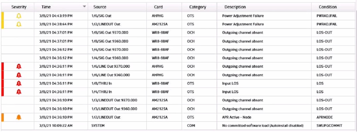
The exhibit shows a conditions list from the 1830 PSS GUI, which displays the alarms and events that occur on the network elements. The total number of alarms reported is equal to the number of rows that have a red or yellow icon in the Severity column, indicating a critical or major alarm. In this case, there are 7 rows with such icons, so the total number of alarms is 7. The number of service affecting alarms is equal to the number of rows that have a ''Yes'' value in the Service Affecting column, indicating that the alarm affects the service quality or availability. In this case, there are 5 rows with such values, so the number of service affecting alarms is 5. The number of conditions is equal to the total number of rows in the table, regardless of their severity or service affecting status. In this case, there are 7 rows in the table, so the number of conditions is 7.Reference:Optical User Guide - Nokia,Security Target Nokia 1830 Photonic Service Switch (PSS)
Consider the exhibit. Given the following power readings, what is the calculated span loss from Node A to Node B?
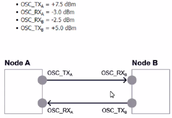
The calculated span loss from Node A to Node B is 10.0 dB. Span loss is the difference between the optical power transmitted and received at two points in a network. It can be calculated by subtracting the received power from the transmitted power. In the exhibit, the transmitted power from Node A to Node B is +7.5 dBm, and the received power at Node B from Node A is -2.5 dBm. Therefore, the span loss is +7.5 dBm - (-2.5 dBm) = 10.0 dB. The other options are incorrect because they do not match the calculation.Reference:Nokia Optical Diagnostics and Troubleshooting Course,Pluggable Optical Modules: Transceivers for the Cisco ONS Family Data Sheet
Suppose a unidirectional amplifier has been plugged into slot 1/13. Which command should the user enter to retrieve the OSC pluggable module type?
The command that the user should enter to retrieve the OSC pluggable module type isshow interface 1/13/OSCSFP detail. This command will display detailed information about the OSC interface on slot 1/13, including the type of pluggable module that is installed in it. The pluggable module type can be either SFP or SFP+, depending on the speed and distance requirements of the OSC link. The command will also show other parameters, such as wavelength, frequency, transmit power, receive power, and status. The other commands are incorrect because they either do not show the pluggable module type or have invalid syntax.Reference:Nokia Optical Diagnostics and Troubleshooting Course,OSFP OCTAL SMALL FORM FACTOR PLUGGABLE MODULE
Suppose a "Channel Absent" alarm is reported on an 1830 PSS node. What is the recommended order for the following troubleshooting steps?
The recommended order for the troubleshooting steps is B, as follows:
Retrieve the channel power trace.This step is useful to identify the affected channel and its power level, as well as to check if there are any fluctuations or anomalies in the power trace that could indicate a channel absent issue1.
Retrieve the cross-connection (XC) details and see what Wave Keys should be present.This step is necessary to verify which Wave Keys are expected to be present on the node, card, and port based on the XC configuration2.Wave Keys are unique identifiers for wavelength tracking that are encoded by Optical Transponders (OTs) into each service wavelength direction3.
Go to the suspected troubled node / card / port and look at Wave Keys (in / out). This step is helpful to compare the observed Wave Keys with the expected Wave Keys, and to locate the source of the problem.If a Wave Key is missing or mismatched, it means that there is a channel absent issue on that node, card, or port4.
Check observed Wave Keys against expected Wave Keys. This step is the final solution to resolve the issue and restore the normal operation of the node. The observed Wave Keys should match the expected Wave Keys based on the XC configuration.If not, the XC configuration should be corrected or the faulty node, card, or port should be replaced5.Reference:Nokia Optical Diagnostics and Troubleshooting Course | Nokia,Optical User Guide - Nokia,Alcatel-Lucent 1830 PSS-8 and PSS-16 Photonic Service Switch
Suppose a Raman amplifier has been plugged into slot 1/8. Which command should the user enter to retrieve the total optical power detected at the ingress interface?
The commandshow interface 1/8/UNEIN detailis used to retrieve the total optical power detected at the ingress interface of a Raman amplifier. This command displays detailed information about the UNEIN interface, which is the unidirectional east input interface of the Raman amplifier.The total optical power detected at the UNEIN interface is shown asInput Power (dBm)in the output of this command1.Reference:Nokia Optical Diagnostics and Troubleshooting Course | Nokia
- Select Question Types you want
- Set your Desired Pass Percentage
- Allocate Time (Hours : Minutes)
- Create Multiple Practice tests with Limited Questions
- Customer Support
Currently there are no comments in this discussion, be the first to comment!