
Free Preparation Discussions
 MENU
MENU
Cisco 800-150 Exam - Topic 6 Question 19 Discussion
Topic #: 6
Refer to the exhibit.
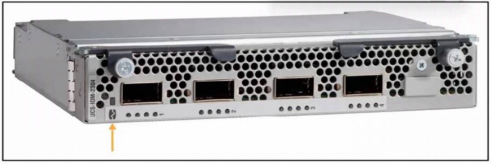
Refer to the exhibit. Which component is highlighted on the Cisco I/O module image?
The highlighted component on the Cisco I/O module is the chassis connections LED, which indicates the status of connectivity between the I/O module and the chassis.
In the exhibit, the orange arrow points to a small rectangular LED indicator located to the left side of the I/O module (Cisco UCS-IOM-2304). This specific LED is not aligned with the ports, fans, or screws, which helps identify it correctly.
Chassis connections LED (B) is responsible for indicating the status of uplink/downlink communication between the I/O module and the chassis.
Green usually indicates a healthy link.
Amber or off may indicate a problem or no connection.
Why the other answers are incorrect:
A . Captive screw These are at the far corners, not where the arrow points.
C . Fan module LED This IOM doesn't have user-visible fan LEDs at the front face.
D . Fixed port These are the large rectangular SFP ports clearly visible in the middle, not near the arrow.
This identification is important when troubleshooting chassis-to-IOM connectivity or verifying module status LEDs during field maintenance.
Doretha
3 days agoLeslie
8 days agoTorie
13 days agoRene
19 days agoGeoffrey
24 days agoKimbery
29 days agoMarcos
1 month agoCorrina
1 month agoMargurite
1 month agoDeandrea
2 months agoBrittni
2 months agoLaticia
2 months agoSanjuana
2 months agoLemuel
2 months agoColetta
4 months agoFranchesca
4 months agoCiara
4 months ago