
Free Preparation Discussions
 MENU
MENU
AutoDesk BIM_MGT_101 Exam Questions
- Topic 1: Corporate standards and documentation: This domain covers establishing firm-wide BIM standards, templates (project, content, and BEP), evaluation of digital tools, documentation of best practices, and development of staff training paths.
- Topic 2: Project needs assessment: This domain covers analyzing client and project BIM requirements, developing and implementing a project-specific BEP, initializing project setup, and applying quality control procedures.
- Topic 3: Collaboration process: This domain covers managing the Common Data Environment, coordinating geolocation across models, overseeing 3D coordination and clash detection, managing multidisciplinary 3D models, and reviewing consultant/subcontractor deliverables.
- Topic 4: Data management: This domain covers ensuring model creation complies with project standards, auditing and resolving model issues, and conducting project closeout including data archiving and handover.
Free AutoDesk BIM_MGT_101 Exam Actual Questions
Note: Premium Questions for BIM_MGT_101 were last updated On Oct. 07, 2026 (see below)
The BIM Execution Plan (BEP) has just been completed for a new project. To ensure all multidisciplinary team members review and understand their roles and responsibilities, what is the most effective way to distribute the BEP before the project starts and ensure it remains accessible to everyone throughout the project?
A mandatory multidisciplinary review session is the strongest method for ensuring that contributors understand the BEP rather than merely receive it. The session allows the BIM manager to explain model ownership, coordination procedures, file structures, software requirements, information exchanges, quality-control responsibilities, naming conventions, issue workflows, and escalation processes. It also enables each discipline to identify ambiguities and confirm acceptance before implementation begins.
Following review and approval, the BEP should be retained as the official controlled project document in the Common Data Environment. This provides an accessible reference and establishes the approved baseline against which later revisions can be tracked.
Uploading a live copy to a shared folder is necessary for accessibility, but distribution alone does not demonstrate that participants understand their obligations. Including the BEP in the contract provides formal status but does not replace operational onboarding. Email signatures confirm receipt or acknowledgment, not comprehension, and can lead to disconnected copies outside the controlled document environment.
The best process combines formal review, multidisciplinary approval, controlled publication, and ongoing accessibility. Among the available choices, option B most completely addresses understanding, agreement, and official document control.
Reference topics: BIM Execution Plan onboarding; multidisciplinary review; roles and responsibilities; controlled documentation; Common Data Environment; approval and revision management.
An AEC company has received a design model from the Architect of Record to begin creating construction documentation. The BIM Execution Plan identifies a fast-track delivery schedule, and the project team includes new consultants with limited exposure to the client's preferred toolset and workflows. The BIM manager must determine how best to prepare the delivery team and assess the model's compatibility with internal systems.
As the BIM manager prepares for the Project Kickoff meeting, which two pieces of information are most critical to avoid issues related to digital compatibility? (Select two.)
Software version and build information is essential because Revit models are not backward-compatible. Opening and saving a model in a newer release upgrades it, potentially preventing teams using an earlier version from accessing the file. Build differences can also matter where hotfixes or updates affect cloud worksharing, interoperability, stability, or specific model functions.
Required add-ins are equally important. A model or workflow may depend on third-party tools for data validation, content placement, exports, parameter management, automation, or specialized object handling. If contributors lack the approved add-in or use incompatible versions, they may be unable to reproduce required processes or may generate inconsistent deliverables.
Project units and shared coordinates are critical for modelling and spatial coordination, but they are project-configuration issues rather than the most direct determinants of digital-tool compatibility. Graphic standards govern presentation and documentation consistency but do not determine whether the model and workflow can be operated within the organization's technology environment.
The kickoff should therefore confirm the approved software release, build, update policy, required add-ins, licensing, installation procedures, and testing responsibilities before production begins.
Reference topics: Software compatibility; Revit version management; approved builds; add-in governance; technology assessment; project kickoff; fast-track mobilization.
The project manager would like to verify Autodesk Forma folder permissions assigned to team members but is not familiar with cloud-sharing platforms to access this information.
How can the BIM manager generate the required information?
The BIM manager should generate an access or permissions report directly from the Autodesk cloud platform. The platform is the authoritative source for project members, folder access levels, assigned roles, and permission configurations. Exporting the report preserves the relationship between the reported information and the actual project configuration while providing the project manager with a format that can be reviewed without navigating the cloud administration interface.
A manually created Word document or spreadsheet would only be a secondary transcription of the permissions. Such records can become inaccurate when users are added, removed, or reassigned, and they provide weaker traceability than a system-generated report. A Revit Show History report records model synchronization activity and user interactions with a workshared model; it does not report cloud-folder permissions.
The exported report should be reviewed for unnecessary access, inconsistent folder inheritance, external-user permissions, and whether each team member has only the level of access required by their role. The BIM manager should also retain the report as part of the project's information-governance and audit records.
Reference topics: Common Data Environment permissions; cloud-user administration; access reporting; information security; role-based access; project audits.
The BIM manager receives an external lighting CAD file to link into the Architectural model and realizes the link is not vertically or horizontally aligned.
What fix needs to happen to resolve this misalignment?
The lighting team should correct the source CAD file so that it conforms to the project's approved coordinate framework and then reissue it. External discipline files must be delivered with a predictable origin, orientation, and elevation that correspond to the architectural or designated site-control model. Correcting the source ensures that every recipient can link the file consistently and that subsequent updates retain the same placement.
Manually moving the linked CAD file in Revit creates an unmanaged instance offset. Although the file may appear aligned temporarily, reloading, replacing, or distributing it can reproduce the original problem or create inconsistent positioning among team members. Adding gridlines may help visually diagnose the offset but does not establish a reliable coordinate relationship.
Acquiring coordinates from the misaligned lighting file is particularly inappropriate because it would redefine the host model's shared-coordinate relationship based on a non-authoritative and incorrectly positioned reference. The architectural or site model should remain the approved source of project positioning.
The BIM manager should provide the lighting team with the agreed coordinate protocol, reference model, control points, units, and required vertical datum, then validate the corrected file before accepting it for coordination.
Reference topics: Consultant file requirements; shared-coordinate governance; CAD-link positioning; authoritative coordinate sources; model exchange; coordination quality control.
A designer needs to add Area Lines in an Area Plan, but upon adding them, they receive a message stating that none of the created elements are visible.
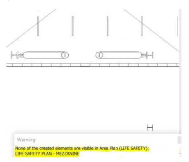
Where can they check to resolve the issue?
The designer should inspect the view's Visibility/Graphics settings. Area Lines, also referred to as Area Boundary Lines, are view-specific elements whose visibility can be controlled by the active view, an applied view template, or category-level visibility settings. If the applicable line category is disabled, Revit can create the boundaries successfully while warning that the newly created elements are not visible in the current Area Plan.
The review should include the Model Categories and Annotation Categories tabs, any active view filters, temporary hide/isolate status, and the view template controlling the Area Plan. Where a template governs visibility, the correction should normally be made in the template rather than as an isolated view override, particularly when the same standard must apply to multiple Area Plans.
A Plan Region changes the local view range and does not govern Area Boundary Line visibility. Detail Level affects how certain model geometry is represented but does not normally suppress Area Lines. The Area Scheme determines the type and organizational purpose of an Area Plan, such as Gross Building or Rentable Area, but it is not the direct location for correcting hidden linework.
Reference topics: Area Plans; Area Boundary Lines; Visibility/Graphics; view templates; view-specific elements; graphical troubleshooting.
- Select Question Types you want
- Set your Desired Pass Percentage
- Allocate Time (Hours : Minutes)
- Create Multiple Practice tests with Limited Questions
- Customer Support
Muhammad Raza
19 days agoEmma Thomas
29 days agoHiroshi Choi
2 months agoYasmin Rahman
2 months agoRichard White
3 months ago